Please enter a keyword to search
Diagram 4.2.2e.: Turning Facilities for Firefighting Appliances
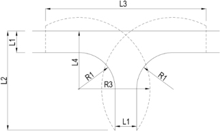
Cul-de-sac turning facility
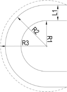
U-turn radii
| Dimensions of Turning Facilities for Firefighting Appliances | |||
| Parameters | Building Habitable Height | ||
| ≤ 10m* | > 10 & ≤ 50m# | > 50m# | |
| R1 | 4.0m | 6.5m | 7.5m |
| R2 | 8.0m | 10.5m | 12.0m |
| R3 | 8.5m | 12.0m | 14.8m |
| L1 | 4.0m | 4.0m | 4.5m |
| L2 | 11.0m | 16.0m | 21.0m |
| L3 | 15.0m | 28.1m | 33.5m |
| L4 | 8.0m | 10.5m | 12.0m |
| Note: * - These dimensions are applicable to all PG except PG VI and VIII buildings, unless otherwise stated in Cl.4.2.2a.(1). For PG VI and VIII buildings ≤ 10m, it shall refer to (> 10 & ≤ 50) requirements, as indicated in Table 4.2C # - Not applicable to PG I buildings. For PG I buildings, it shall refer to (≤ 10m) requirements | |||
Diagram 4.2.2e.: Turning facilities for firefighting appliances
Diagram 4.2.2f.: Building Structure over Fire Engine Accessway/ Fire Engine Access Road
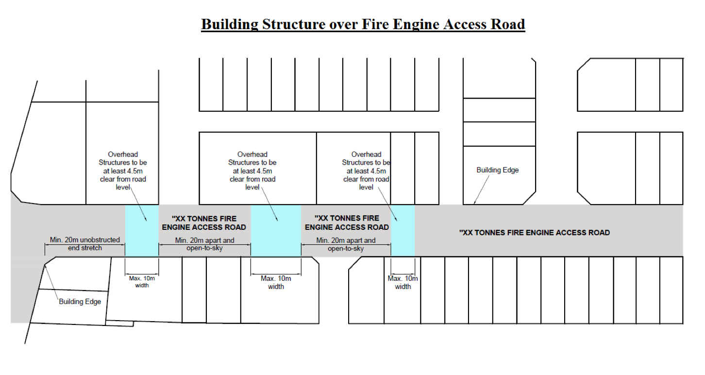
Diagram 4.2.2i.(2): Marking of fire engine accessway/ fire engine access road
-26-jan-2(concurred-with-sia-ops).jpg?sfvrsn=6a732c4b_1)
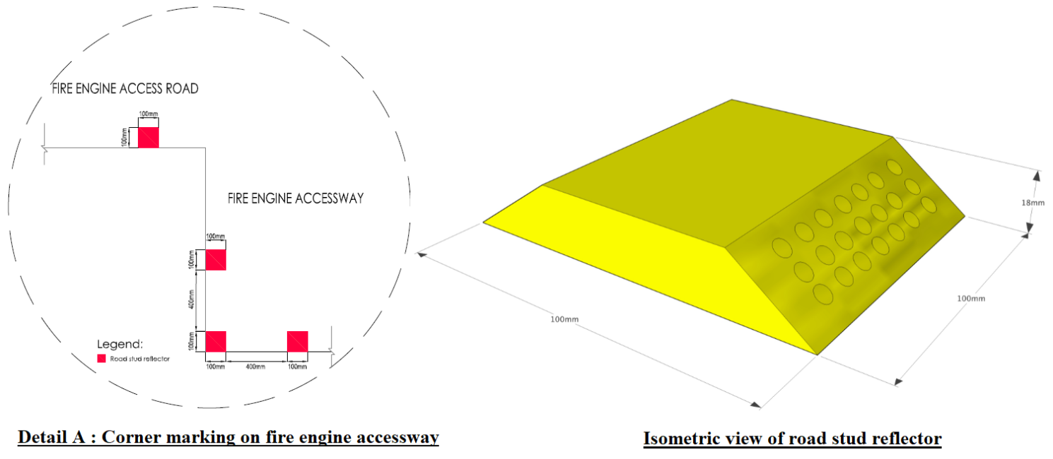
Diagram 4.2.2i.(2): Marking of fire engine accessway/ fire engine access road
Diagram 4.2.2i.(3): Pictogram signage for fire engine accessway/ fire engine access road
.png?sfvrsn=952396ba_1)
Diagram 4.2.2i.(3): Pictogram signage for fire engine accessway/ fire engine access road
Diagram 4.2.2j.(1) - 1 & 2
---1.png?sfvrsn=f6211519_1)
Diagram 4.2.2j.(1) - 1: CPL 34 firefighting appliance - Wheels & jacks layout
---2.png?sfvrsn=bb41ddd1_1)
Diagram 4.2.2j.(1) - 2: AL 56 & CPL 60 firefighting appliances - Wheels & jacks layout
Diagram 4.2.2j.(3) - 3: HLA 90 firefighting appliance - Wheels & jacks layout
---3.png?sfvrsn=bce226bf_1)
Diagram 4.2.2j.(3) - 3: HLA 90 firefighting appliance - Wheels & jacks layout
Diagram 4.2.2l. Bi-directional fire engine accessway/fire engine access road
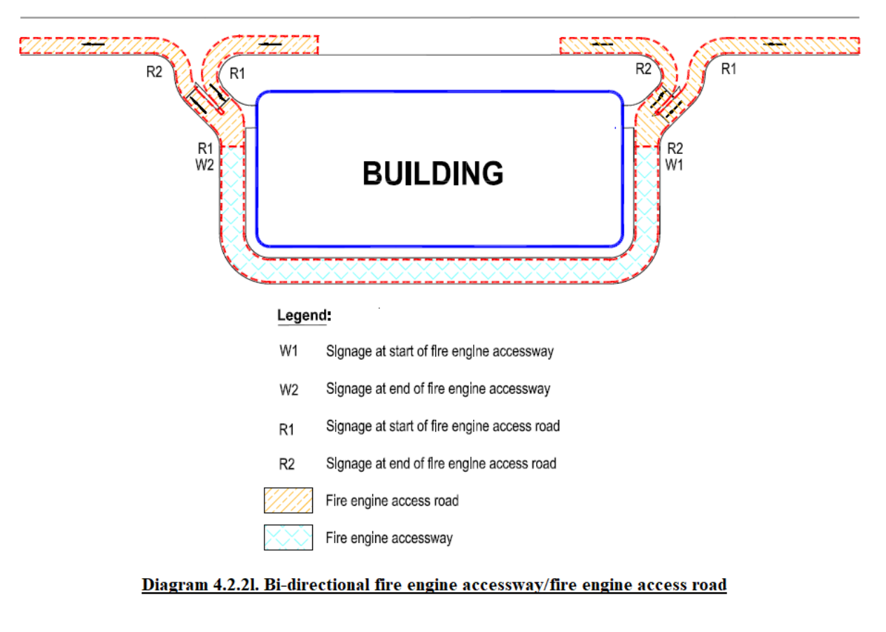
Diagram 4.4.1a.: Provision of private fire hydrant
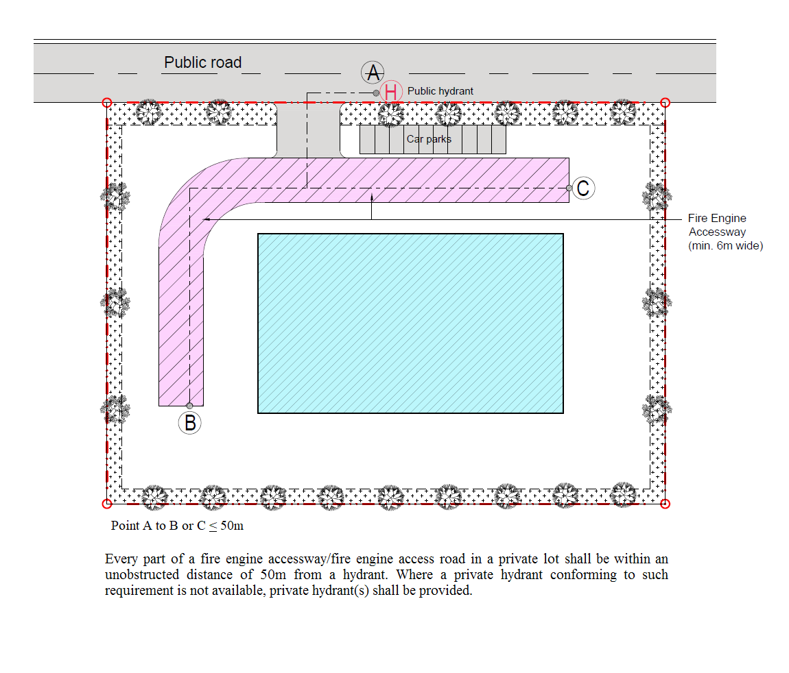
Diagram 4.4.1a.: Provision of private fire hydrant
Provision of Private Hydrant
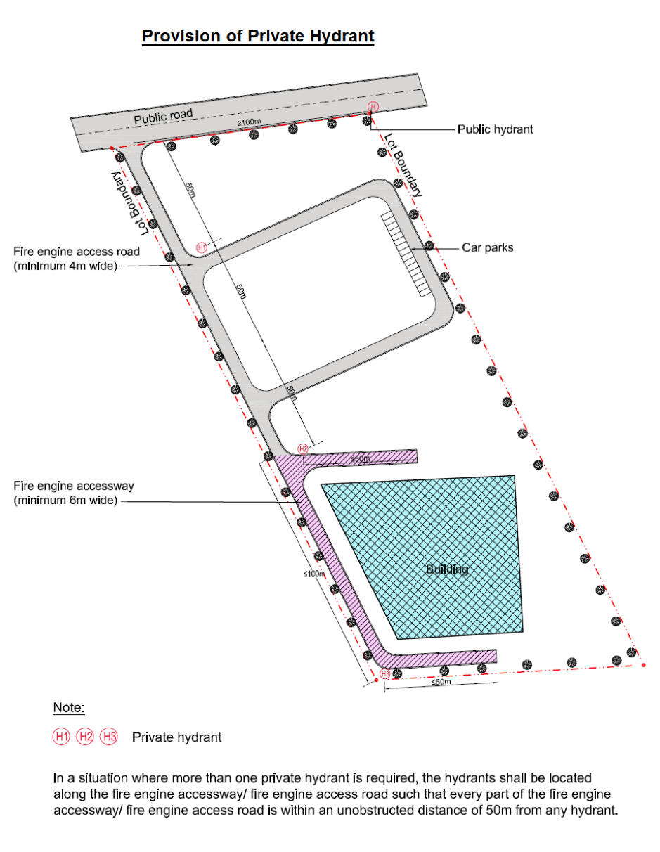
Diagram 4.4.1c.: Siting of private fire hydrant
TABLE 4.2A: FIRE ENGINE ACCESSWAY/FIRE ENGINE ACCESS ROAD FOR PG II BUILDINGS
| TABLE 4.2A: FIRE ENGINE ACCESSWAY/FIRE ENGINE ACCESS ROAD FOR PG II BUILDINGS | |||
| Details | Habitable Height (m) | ||
| ≤ 10 | > 10 & ≤ 50 | > 50 | |
| Width of fire engine access road | > 4m | ||
| Width of fire engine accessway* | Not required | > 6m | > 7m |
| Length of fire engine accessway* | - | > 15m | > 15m |
| Type of firefighting appliance | Pump ladder | CPL 34 & AL 56 | AL 56, CPL 60 & HLA 90 |
| Loading capacity of fire engine road# | > 24 tonnes | > 30 tonnes | > 50 tonnes |
| Loading capacity of fire engine accessway# | - | > 30 tonnes | > 50 tonnes |
| Axle/ Jack loading | - | See Table 4.2D & Table 4.2E | |
| Turning facility | See Diagram 4.2.2e. | ||
| U-turn radii | |||
|
Note: # - The appended figures for loading capacity of fire engine accessway/ fire engine access road are characteristic values * - A fire engine accessway of at least ¼ length of perimeter (minimum 15m), whichever is greater, shall be provided to access at least one facade of each block |
|||
TABLE 4.2B: FIRE ENGINE ACCESSWAY/FIRE ENGINE ACCESS ROAD FOR PG III, IV, V & VII BUILDINGS
| TABLE 4.2B: FIRE ENGINE ACCESSWAY/FIRE ENGINE ACCESS ROAD FOR PG III, IV, V & VII BUILDINGS | |||
| Details | Habitable Height (m) | ||
| ≤ 10 | > 10 & ≤ 50 | > 50 | |
| Width of fire engine access road | > 4m | ||
| Width of fire engine accessway | Not required | > 6m | > 7m |
| Length of fire engine accessway | - | See Table 4.2.2a.(6) | |
| Type of firefighting appliance | Pump ladder | CPL 34 & AL 56 | AL 56, CPL 60 & HLA 90 |
| Loading capacity of fire engine access road# | > 24 tonnes | > 30 tonnes | > 50 tonnes |
| Loading capacity of fire engine accessway# | - | > 30 tonnes | > 50 tonnes |
| Axle/ Jack loading | - | See Table 4.2D & Table 4.2E | |
| Turning facility | See Diagram 4.2.2e. | ||
| U-turn radii | |||
|
Note: # = The appended figures for loading capacity of fire engine accessway/ fire engine access road are characteristic values |
|||
TABLE 4.2C: FIRE ENGINE ACCESSWAY/FIRE ENGINE ACCESS ROAD FOR PG VI & VIII BUILDINGS
| TABLE 4.2C: FIRE ENGINE ACCESSWAY/FIRE ENGINE ACCESS ROAD FOR PG VI & VIII BUILDINGS | |||
| Details | Habitable Height (m) | ||
| ≤ 10 | > 10 & ≤ 50 | > 50 | |
| Width of fire engine access road | > 4m | ||
| Width of fire engine accessway | > 6m | > 6m | > 7m |
| Length of fire engine accessway | See Table 4.2.2a.(7) | ||
| Type of firefighting appliance | CPL 34 & AL 56 | CPL 34 & AL 56 | AL 56, CPL 60 & HLA 90 |
| Loading capacity of fire engine access road# | > 30 tonnes | > 30 tonnes | > 50 tonnes |
| Loading capacity of fire engine accessway# | > 30 tonnes | > 30 tonnes | > 50 tonnes |
| Axle/ Jack loading | See Table 4.2D & Table 4.2E | ||
| Turning facility |
See Diagram 4.2.2e. under (>10 & ≤50) |
See Diagram 4.2.2e. | |
| U-turn radii | |||
|
Note: # = The appended figures for loading capacity of fire engine accessway/ fire engine access road are characteristic values |
|||
TABLE 4.2D: AXLE LOADING OF FIREFIGHTING APPLIANCES
| TABLE 4.2D: AXLE LOADING OF FIREFIGHTING APPLIANCES | ||||||||||
| Axle No. (from font) | Type of firefighting appliances | |||||||||
| Pump Ladder | CPL 34 | AL 56 | CPL 60 | HLA 90 | ||||||
| Loading Wt. (kg) | No of wheels | Loading Wt. (kg) | No of wheels | Loading Wt. (kg) | No of wheels | Loading Wt. (kg) | No of wheels | Loading Wt. (kg) | No of wheels | |
| Axle 1 | 10000 | 2 | 7500 | 2 | 9000 | 2 | 9000 | 2 | 9000 | 2 |
| Axle 2 | 14000 | 2 | 10500 | 2 | 10500 | 4 | 9900 | 4 | 9000 | 2 |
| Axle 3 | - | - | 10500 | 4 | 10500 | 4 | 9900 | 4 | 10500 | 4 |
| Axle 4 | - | - | - | - | - | - | 8200 | 2 | 10500 | 4 |
| Axle 5 | - | - | - | - | - | - | - | - | 10000 | 2 |
| Axle 6 | - | - | - | - | - | - | - | - | - | - |
Note: The appended figures for axle loading are characteristic values | ||||||||||
TABLE 4.2E: JACK LOADING OF FIREFIGHTING APPLIANCES
| TABLE 4.2E: JACK LOADING OF FIREFIGHTING APPLIANCES | ||||
| Type of Fire Appliance | CPL 34 | AL 56 | CPL 60 | HLA 90 |
| Jack load contact area | 5625 cm2 | 5625 cm2 | 7125 cm2 | 7125 cm2 |
| Maximum pressure per Jack (4 jacks per vehicle) | 37 N/cm2 | 37 N/cm2 | 37 N/cm2 | 50 N/cm2 |
|
Note: The appended figures for jack loading are characteristic values |
||||
TABLE 4.4A: WATER SUPPLY & STORAGE REQUIREMENTS FOR PRIVATE FIRE HYDRANT
| TABLE 4.4A: WATER SUPPLY & STORAGE REQUIREMENTS FOR PRIVATE FIRE HYDRANT | ||||
| Purpose Group | Accessible Floor Area* | Minimum Flow Rate | Minimum Running Pressure | Minimum Water supply and Storage Duration |
| (m2) | (L/s) | (bar) | (mins) | |
| PG I & II | - | 27 | 2 | 45 |
| Covered car park not within PG VI & VIII buildings + | NL | 38 | 2 | 45 |
| PG III, IV, V & VII | ≤ 1000 | 38 | 2 | 45 |
| > 1000 & ≤ 5000 | 57 | |||
| > 5000 & ≤ 10000 | 76 | |||
| > 10000 | 95 | |||
| PG VI & VIII | ≤ 500 | 38 | 2 | 90 |
| > 500 & ≤ 5000 | 57 | |||
| > 5000 & ≤ 10000 | 76 | |||
| > 10000 & ≤ 15000 | 95 | |||
| > 15000 & ≤ 20000 | 114 | |||
| > 20000 | 133 | |||
|
Note: NL - No limit * - Based on the Accessible Floor Area (AFA) of the largest compartment in the building + - This requirement is only applicable to car parking facilities within PG II, III, IV, V & VII buildings, either as a standalone multi-storey car park or within a building (above ground or below ground). The hydrant requirements for the remaining parts of the buildings shall comply with Cl.4.4.2a., Cl.4.4.2b. and Cl.4.4.2c. |
||||
Updated 3 Sep 2025
