Please enter a keyword to search
4.4.1 Provision of private fire hydrant
a. General
Every part of a fire engine accessway and/ or fire engine access road shall be within an unobstructed distance of 50m from a fire hydrant. Where a public fire hydrant conforming to this requirement is not available, private fire hydrant(s) shall be provided. See Diagram 4.4.1a..
b. Use of public fire hydrant
Existing public fire hydrants along one side of a public road shall not be designated to serve developments sited on the other side of the public road, except for a road having at most two lanes, regardless of traffic direction.
c. Locations of fire hydrants
In situations where more than one private fire hydrants is required, the fire hydrants shall be located along the fire engine accessway/ fire engine access road such that every part of the fire engine accessway/ fire engine access road is within an unobstructed distance of 50m from any fire hydrant. See Diagram 4.4.1c..
d. Siting and types of fire hydrants
Siting and types of fire hydrants shall comply with the requirements stated in SS 575.
e. Ringed fire hydrant pipes
For a building that is required to have an island site fire engine accessway the fire hydrant pipe shall be a ring system. Isolation valves shall be provided on the fire hydrant ring such that on any section of ring, not more than one fire hydrant can be isolated when required for maintenance without affecting the water supply (both designed pressure and flow) to the other fire hydrants on the ring.
f. Valve locking device
A locking device shall be provided to lock the valves in open position during normal operation. Underground valves shall be kept in an open position at all times.
4.4.2 Water supply for private fire hydrant
The provision of water supply for a private fire hydrant system, where required by this Code, shall comply with the following requirements
a. Private fire hydrant at or below reduced level 125m
(1) Private fire hydrants installed at reduced level 125m and below can receive direct supply from public water mains provided the flow and pressure from the public water mains meet the fire hydrant requirements as shown in Table 4.4A, or the following requirements are complied with:
(a) the AFA of the largest compartment shall not exceed 1000m2 for PG III, IV, V & VII and not exceed 500m2 for PG VI & VIII buildings. No AFA limit for covered car park in PG II, III, IV, V & VII buildings;
(b) the nominal bore of the fire hydrant pipe and the bulk water meter shall not be less than 150mm in diameter; and
(c) the running pressure/flow at the hydraulically most unfavourable fire hydrant of the private fire hydrant system shall comply with the following:
(i) running pressure >= 0.9 x (running pressure of the nearest public fire hydrant – pressure drop across the bulk water metre); and
(ii) flow rate >= 0.9 x water flow of the nearest public fire hydrant or >= total
flow demand (as required in Table 4.4A)
of the private fire hydrant system, provided the running pressure at the most remote private fire hydrant is greater than 2 bars.
Note:
In calculating the frictional loss for the private fire hydrant system, the design flow rates shown in Table 4.4A shall
be used. The pressure drop across bulk water metre shall not be more than 1 bar.
(2) If the requirements stipulated in Cl.4.4.2a.(1) cannot be met, a storage tank of sufficient capacity meeting the flow rate and duration as specified in Table 4.4A with the requisite pumping facilities shall be provided.
b. Private fire hydrant above reduced level 125m
(1) Where more than one private fire hydrant is located above reduced level 125m within the same plot, storage and pumping arrangements of water supply to these specified fire hydrants shall comply with the requirements stipulated in Cl.4.4.2c..
(2) The private fire hydrant can be in the form of a dry fire hydrant, if it is not the sole fire hydrant within 50m from any breeching inlet(s) feeding firefighting systems for the building(s) within the plot of land, which include:
(a) automatic fire sprinkler systems, or
(b) dry riser systems, or
(c) wet riser systems.
(3) A dry fire hydrant shall comply with all of the following requirements:
(a) A dry private fire hydrant shall be connected to a 150mm diameter dry pipe, which shall be connected at the other end to a four-way breeching inlet.
(b) This breeching inlet shall be within 18m from any fire engine accessway/fire engine access road having minimum 4m width and within 50m from any wet fire hydrant, private or public.
(c) The private dry pillar shall be painted in “yellow” and labelled “dry” on the fire hydrant pillar.
(d) A signage indicating the location of breeching inlet shall be positioned next to the dry private fire hydrant.
c. Water supply and storage requirement
Where more than one private fire hydrant is located above reduced level 125m within the same plot, storage and pumping arrangements of water supply to these specified fire hydrants shall comply with those for wet rising mains stipulated in SS 575 and Table 4.4A Water Supply & Storage Requirements for Private Fire Hydrant.
4.4.3 Protection of fire hydrant mains in buildings
All fire hydrant mains which pass through a building shall have its full length within the building protected with fire resistance construction complying with Cl.3.8.7b. of at least the same fire resistance as the element of structure, provided all of the following requirements are complied with:
a. The fire hydrant mains shall be located in common circulation areas, such as car parking spaces (except spaces used for mechanical car parking) and driveways, i.e. they shall not pass through private or confined spaces.
b. No services other than sprinkler pipe(s) shall be located above or crossing over the fire hydrant mains. Where services need to cross-over the hydrant mains, the following conditions shall be complied with:
(1) the services shall only cross over the fire hydrants mains perpendicularly;
(2) the tensile stress of the supports for the services shall not exceed 10N/mm2; and
(3) the services shall be adequately protected by the building’s sprinkler system.
c. The fire hydrant mains shall be located away from explosion risk areas.
d. The protective enclosure to the fire hydrant mains shall be labelled with the words “FIRE HYDRANT MAIN” of minimum 50mm height at suitable intervals.
Cul-de-sac turning facility
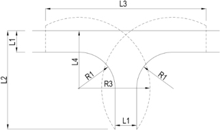
Cul-de-sac turning facility
U-turn radii
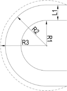
U-turn radii
Dimensions of Turning Facilities for Firefighting Appliances
| Dimensions of Turning Facilities for Firefighting Appliances | |||
| Parameters | Building Habitable Height | ||
| ≤ 10m* | > 10 & ≤ 50m# | > 50m# | |
| R1 | 4.0m | 6.5m | 7.5m |
| R2 | 8.0m | 10.5m | 12.0m |
| R3 | 8.5m | 12.0m | 14.8m |
| L1 | 4.0m | 4.0m | 4.5m |
| L2 | 11.0m | 16.0m | 21.0m |
| L3 | 15.0m | 28.1m | 33.5m |
| L4 | 8.0m | 10.5m | 12.0m |
| Note: * - These dimensions are applicable to all PG except PG VI and VIII buildings, unless otherwise stated in Cl.4.2.2a.(1). For PG VI and VIII buildings ≤ 10m, it shall refer to (> 10 & ≤ 50) requirements, as indicated in Table 4.2C # - Not applicable to PG I buildings. For PG I buildings, it shall refer to (≤ 10m) requirements | |||
Diagram 4.2.2e.: Turning facilities for firefighting appliances
Building Structure over Fire Engine Access Road
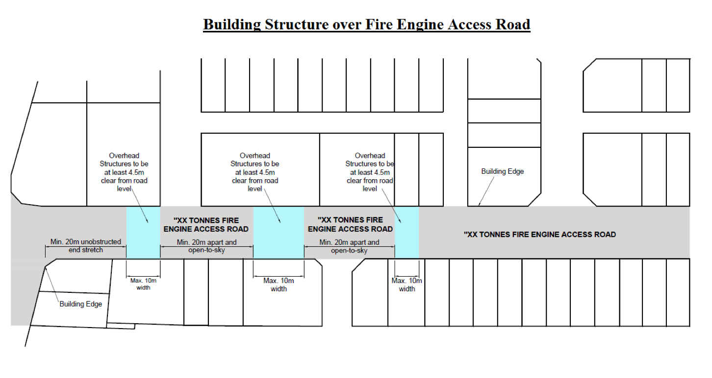
Diagram 4.2.2f.: Building structure over fire engine accessway/ fire engine access road
Diagram 4.2.2i.(2): Marking of fire engine accessway/ fire engine access road
-26-jan-2(concurred-with-sia-ops).jpg?sfvrsn=6a732c4b_1)
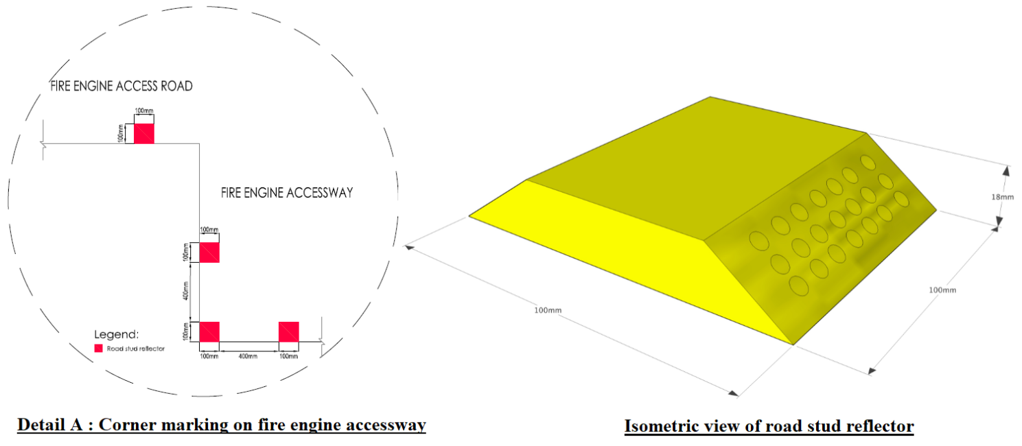
Diagram 4.2.2i.(2): Marking of fire engine accessway/ fire engine access road
Diagram 4.2.2i.(3): Pictogram signage for fire engine accessway/ fire engine access road
.png?sfvrsn=952396ba_1)
Diagram 4.2.2i.(3): Pictogram signage for fire engine accessway/ fire engine access road
Diagram 4.2.2j.(1) - 1 & 2
---1.png?sfvrsn=f6211519_1)
Diagram 4.2.2j.(1) - 1: CPL 34 firefighting appliance - Wheels & jacks layout
---2.png?sfvrsn=bb41ddd1_1)
Diagram 4.2.2j.(1) - 2: AL 56 & CPL 60 firefighting appliances - Wheels & jacks layout
Diagram 4.2.2j.(3) - 3: HLA 90 firefighting appliance - Wheels & jacks layout
---3.png?sfvrsn=bce226bf_1)
Diagram 4.2.2j.(3) - 3: HLA 90 firefighting appliance - Wheels & jacks layout
Diagram 4.2.2l. Bi-directional fire engine accessway/fire engine access road
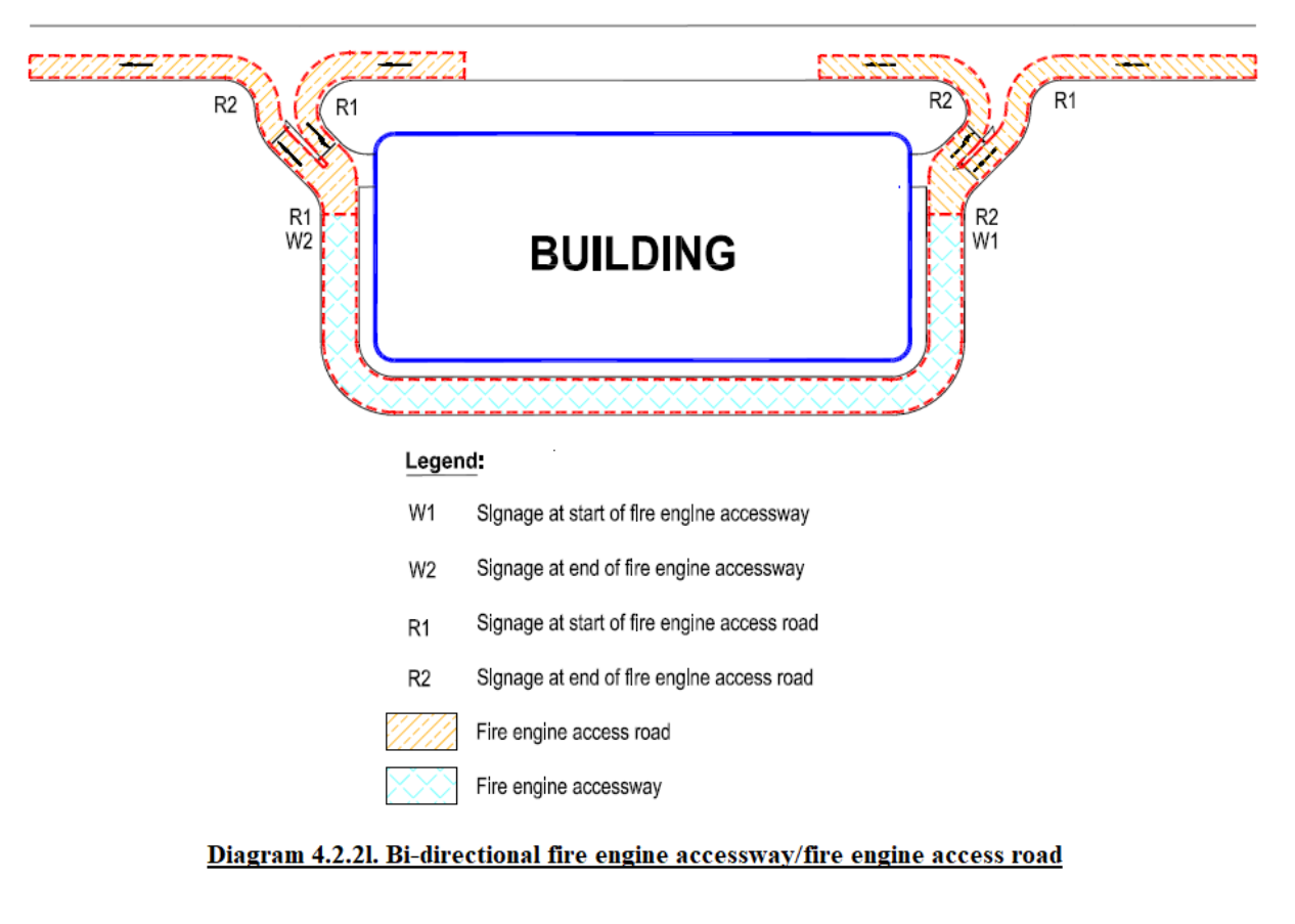
Diagram 4.4.1a.: Provision of private fire hydrant
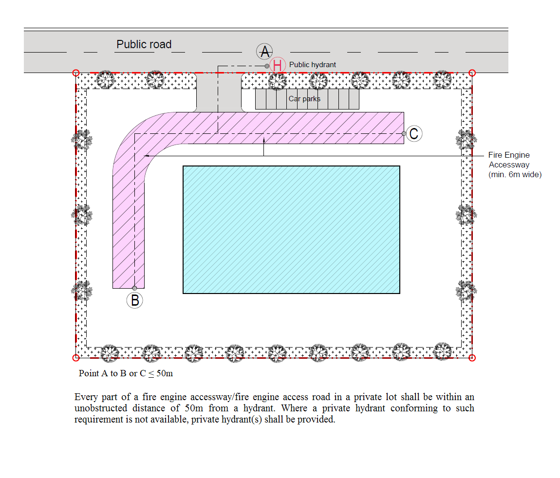
Diagram 4.4.1a.: Provision of private fire hydrant
Provision of Private Hydrant
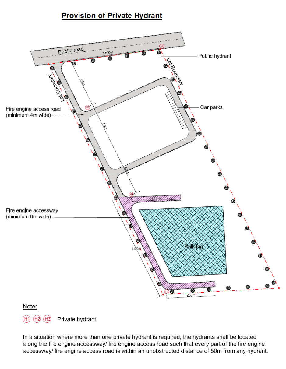
Diagram 4.4.1c.: Siting of private fire hydrant
TABLE 4.2A: FIRE ENGINE ACCESSWAY/FIRE ENGINE ACCESS ROAD FOR PG II BUILDINGS
| TABLE 4.2A: FIRE ENGINE ACCESSWAY/FIRE ENGINE ACCESS ROAD FOR PG II BUILDINGS | |||
| Details | Habitable Height (m) | ||
| ≤ 10 | > 10 & ≤ 50 | > 50 | |
| Width of fire engine access road | ≥ 4m | ||
| Width of fire engine accessway* | Not required | ≥ 6m | ≥ 7m |
| Length of fire engine accessway* | - | ≥ 15m | ≥ 15m |
| Type of firefighting appliance | Pump ladder | CPL 34 & AL 56 | AL 56, CPL 60 & HLA 90 |
| Loading capacity of fire engine road# | ≥ 24 tonnes | ≥ 30 tonnes | ≥ 50 tonnes |
| Loading capacity of fire engine accessway# | - | ≥ 30 tonnes | ≥ 50 tonnes |
| Axle/ Jack loading | - | See Table 4.2D & Table 4.2E | |
| Turning facility | See Diagram 4.2.2e. | ||
| U-turn radii | |||
Note: # - The appended figures for loading capacity of fire engine accessway/ fire engine access road are characteristic values * - A fire engine accessway of at least ¼ length of perimeter (minimum 15m), whichever is greater, shall be provided to access at least one facade of each block | |||
TABLE 4.2B: FIRE ENGINE ACCESSWAY/FIRE ENGINE ACCESS ROAD FOR PG III, IV, V & VII BUILDINGS
| TABLE 4.2B: FIRE ENGINE ACCESSWAY/FIRE ENGINE ACCESS ROAD FOR PG III, IV, V & VII BUILDINGS | |||
| Details | Habitable Height (m) | ||
| ≤ 10 | > 10 & ≤ 50 | > 50 | |
| Width of fire engine access road | ≥ 4m | ||
| Width of fire engine accessway | Not required | ≥ 6m | ≥ 7m |
| Length of fire engine accessway | - | See Table 4.2.2a.(6) | |
| Type of firefighting appliance | Pump ladder | CPL 34 & AL 56 | AL 56, CPL 60 & HLA 90 |
| Loading capacity of fire engine access road# | ≥ 24 tonnes | ≥ 30 tonnes | ≥ 50 tonnes |
| Loading capacity of fire engine accessway# | - | ≥ 30 tonnes | ≥ 50 tonnes |
| Axle/ Jack loading | - | See Table 4.2D & Table 4.2E | |
| Turning facility | See Diagram 4.2.2e. | ||
| U-turn radii | |||
Note: # = The appended figures for loading capacity of fire engine accessway/ fire engine access road are characteristic values | |||
TABLE 4.2C: FIRE ENGINE ACCESSWAY/FIRE ENGINE ACCESS ROAD FOR PG VI & VIII BUILDINGS
| TABLE 4.2C: FIRE ENGINE ACCESSWAY/FIRE ENGINE ACCESS ROAD FOR PG VI & VIII BUILDINGS | |||
| Details | Habitable Height (m) | ||
| ≤ 10 | > 10 & ≤ 50 | > 50 | |
| Width of fire engine access road | ≥ 4m | ||
| Width of fire engine accessway | ≥ 6m | ≥ 6m | ≥ 7m |
| Length of fire engine accessway | See Table 4.2.2a.(7) | ||
| Type of firefighting appliance | CPL 34 & AL 56 | CPL 34 & AL 56 | AL 56, CPL 60 & HLA 90 |
| Loading capacity of fire engine access road# | ≥ 30 tonnes | ≥ 30 tonnes | ≥ 50 tonnes |
| Loading capacity of fire engine accessway# | ≥ 30 tonnes | ≥ 30 tonnes | ≥ 50 tonnes |
| Axle/ Jack loading | See Table 4.2D & Table 4.2E | ||
| Turning facility | See Diagram 4.2.2e. under (>10 & ≤50) | See Diagram 4.2.2e. | |
| U-turn radii | |||
Note: # = The appended figures for loading capacity of fire engine accessway/ fire engine access road are characteristic values | |||
TABLE 4.2D: AXLE LOADING OF FIREFIGHTING APPLIANCES
| TABLE 4.2D: AXLE LOADING OF FIREFIGHTING APPLIANCES | ||||||||||
| Axle No. (from font) | Type of firefighting appliances | |||||||||
| Pump Ladder | CPL 34 | AL 56 | CPL 60 | HLA 90 | ||||||
| Loading Wt. (kg) | No of wheels | Loading Wt. (kg) | No of wheels | Loading Wt. (kg) | No of wheels | Loading Wt. (kg) | No of wheels | Loading Wt. (kg) | No of wheels | |
| Axle 1 | 10000 | 2 | 7500 | 2 | 9000 | 2 | 9000 | 2 | 9000 | 2 |
| Axle 2 | 14000 | 2 | 10500 | 2 | 10500 | 4 | 9900 | 4 | 9000 | 2 |
| Axle 3 | - | - | 10500 | 4 | 10500 | 4 | 9900 | 4 | 10500 | 4 |
| Axle 4 | - | - | - | - | - | - | 8200 | 2 | 10500 | 4 |
| Axle 5 | - | - | - | - | - | - | - | - | 10000 | 2 |
| Axle 6 | - | - | - | - | - | - | - | - | - | - |
Note: The appended figures for axle loading are characteristic values | ||||||||||
TABLE 4.2E: JACK LOADING OF FIREFIGHTING APPLIANCES
| TABLE 4.2E: JACK LOADING OF FIREFIGHTING APPLIANCES | ||||
| Type of Fire Appliance | CPL 34 | AL 56 | CPL 60 | HLA 90 |
| Jack load contact area | 5625 cm2 | 5625 cm2 | 7125 cm2 | 7125 cm2 |
| Maximum pressure per Jack (4 jacks per vehicle) | 37 N/cm2 | 37 N/cm2 | 37 N/cm2 | 50 N/cm2 |
|
Note: The appended figures for jack loading are characteristic values |
||||
TABLE 4.4A: WATER SUPPLY & STORAGE REQUIREMENTS FOR PRIVATE FIRE HYDRANT
| TABLE 4.4A: WATER SUPPLY & STORAGE REQUIREMENTS FOR PRIVATE FIRE HYDRANT | ||||
| Purpose Group | Accessible Floor Area* | Minimum Flow Rate | Minimum Running Pressure | Minimum Water supply and Storage Duration |
| (m2) | (L/s) | (bar) | (mins) | |
| PG I & II | - | 27 | 2 | 45 |
| Covered car park not within PG VI & VIII buildings + | NL | 38 | 2 | 45 |
| PG III, IV, V & VII | ≤ 1000 | 38 | 2 | 45 |
| > 1000 & ≤ 5000 | 57 | |||
| > 5000 & ≤ 10000 | 76 | |||
| > 10000 | 95 | |||
| PG VI & VIII | ≤ 500 | 38 | 2 | 90 |
| > 500 & ≤ 5000 | 57 | |||
| > 5000 & ≤ 10000 | 76 | |||
| > 10000 & ≤ 15000 | 95 | |||
| > 15000 & ≤ 20000 | 114 | |||
| > 20000 | 133 | |||
|
Note: NL - No limit * - Based on the Accessible Floor Area (AFA) of the largest compartment in the building + - This requirement is only applicable to car parking facilities within PG II, III, IV, V & VII buildings, either as a standalone multi-storey car park or within a building (above ground or below ground). The hydrant requirements for the remaining parts of the buildings shall comply with Cl.4.4.2a., Cl.4.4.2b. and Cl.4.4.2c. |
||||
Updated 3 Mar 2025
