In conjunction with Part 20, methods of test are provided for – Beams, columns, floors, flat roofs and walls (Part 21); Partitions, door sets and vertical shutter assemblies, ceiling membranes and glazed elements (Part 22); and Suspended ceilings
protecting steel beams and intumescent seals for use in conjunction with single acting latched timber fire-resisting door assemblies (Part 23).
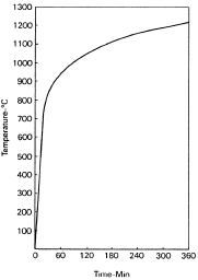
Part 20 specifies standard heating conditions based on a temperature/time curve (Figure 3.4.1 - 2) which furnaces are required to follow; the temperature at defined locations close to the exposed face of the specimen under test rising
to 821°C after 30 minutes and 1133°C after four hours.

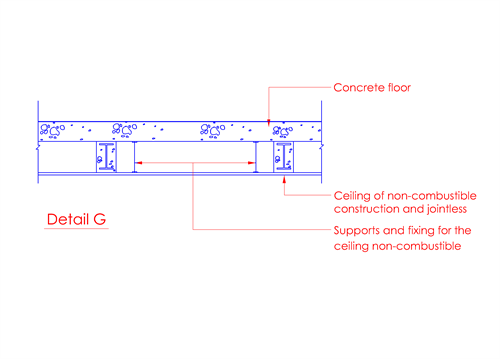
Figure 3.4.1 - 1

Figure 3.4.1 - 2 : Standard temperature vs Time curve
The specimen to be tested should be either full size or, where the element exceeds the size that can be accommodated by the furnace, it must have the following minimum dimensions.
Non-separating elements: Vertical 3m high Horizontal 4m span
Separating elements: Vertical 3m high X 3m wide Horizontal 4m high X 3m wide
Specimens are normally heated to simulate their exposure in a fire, e.g. walls from one side, floors from beneath and columns from all sides.
Elements of building construction are required to satisfy various criteria according to their designed function in the event of fire. These are:
a. “Stability” or “Load-bearing capacity”: the ability of a load-bearing element to support its test load without excessive deflection.
b. “Integrity”: the ability of a separating element to resist collapse, the formation of holes, gaps or fissures through which flames and/or hot gases could pass, and the occurrence of sustained flaming on the unexposed face (the side of the
specimen remote from the furnace).
c. “Insulation”: the ability of a separating element to resist an excessive rise in temperature on its unexposed face.
The criterion of “stability” or “load-bearing capacity” is applied only to load-bearing elements. For floors, flat roofs and beams, allowable vertical deflection is limited to 1⁄20 clear span.
Loss of “integrity” in the context of the formation of holes, gaps or fissures is judged by ignition of a cotton fibre pad. Where this test is not suitable, failure is deemed to have occurred if either a 25mm diameter gauge can penetrate into
the furnace through a gap at any point, or a 6mm diameter gauge can penetrate into the furnace through an opening and can be moved for a distance of at least 150mm.
Loss of “insulation” occurs when the temperature on the unexposed face (the side of the specimen remote from the furnace) increases by more than 140°C (mean) or by more than 180°C at any point. Loss of “integrity” also
constitutes loss of “insulation”.
Columns and beams have to satisfy only the criterion of “load-bearing capacity”; glazed elements are normally required to satisfy only “integrity”; and floors and walls have to satisfy all three criteria. It is pertinent to note
that under Table 3.4A, doors are only required to satisfy “integrity”,
leaving aside “insulation” as it is assumed unlikely that combustible materials would be stored against them. However, doors to protected lobbies, exit staircases and exit passageways should be provided with insulation against transmission
of heat by radiation from the fire floor into the protected enclosures which occupants use for evacuation.
It is important to note that fire-rated glass door shall not be used in fire lift shaft, exit staircases and exit passageways. In other areas such as protected lobbies, separating and compartment walls, the use of fire-rated glass is permitted, provided
the building is sprinkler-protected. See Cl.3.15.13 for
more details.

