ANNEX 2A
EXITING ANALYSIS
A.1 GENERAL
A.1.1 Evacuation times
As described in Chapter 2, there shall be sufficient exit capacity to clear the platform occupant load from the station platform in 4 minutes or less, and the station shall be designed to permit evacuation from the most remote point of the platform to a point of safety in 6 minutes or less.
A.1.2 Time to clear platform/ Platform exits flow time
Platform exit time is the time required to clear all the platform occupant load from the platform according to the formula:
Time to clear platform
= Platform exits flow time
= Platform Occupant Load/ Platform Exit Capacity
A.1.3 Station evacuation time
The time to evacuate from the most remote point of the platform to a point of safety is the sum of the walking travel time for the longest exit route plus the waiting time at the various circulation elements.
A.1.4 Walking travel time
The walking travel time is calculated using station geometry data and the travel speeds indicated in Cl.2.2.3h.. The exit route is broken down into segments and tabulated. The travel distance for each segment is then divided by the appropriate travel speed to determine the time needed to traverse each segment. The walking travel time is the sum of the times for each segment.
A.1.5 Flow time
The flow time (the time for the last person to through the particular element) for each of the various circulation elements (e.g. stairs/ escalators, fare collection gates, doors, etc.) is calculated using the capacities and conditions specified in Chapter 2.
A.1.6 Care must be taken to be sure that the most restrictive circulation elements are included in the calculations.
For instance, if a 1m wide single-leaf door provides access to a 1.2m wide stair, the door and the stair would be considered to provide a capacity of 80p/min and 72p/min respectively in accordance with Cl.2.2.3h.. In this case the stair is more restrictive than the door, meaning that the stair shall be used in the capacity calculation.
A.1.7 Where exit paths divide, i.e. where a choice of exit paths is presented, it is presumed that the passengers will divide into groups roughly in proportion to the exit capacity provided by the various paths at the decision point. It also is presumed that passengers, once having made a decision (selecting an exit path), will stay on that path until another decision point is reached or egress is achieved.
A.1.8 Waiting time of circulation elements
The waiting time at each of the various circulation elements is calculated, for the platform exits, by subtracting the walking travel time on the platform from the platform exits flow time, and for each of the remaining circulation elements, by subtracting the maximum of all previous element flow times.
A.2 CENTRE PLATFORM STATION
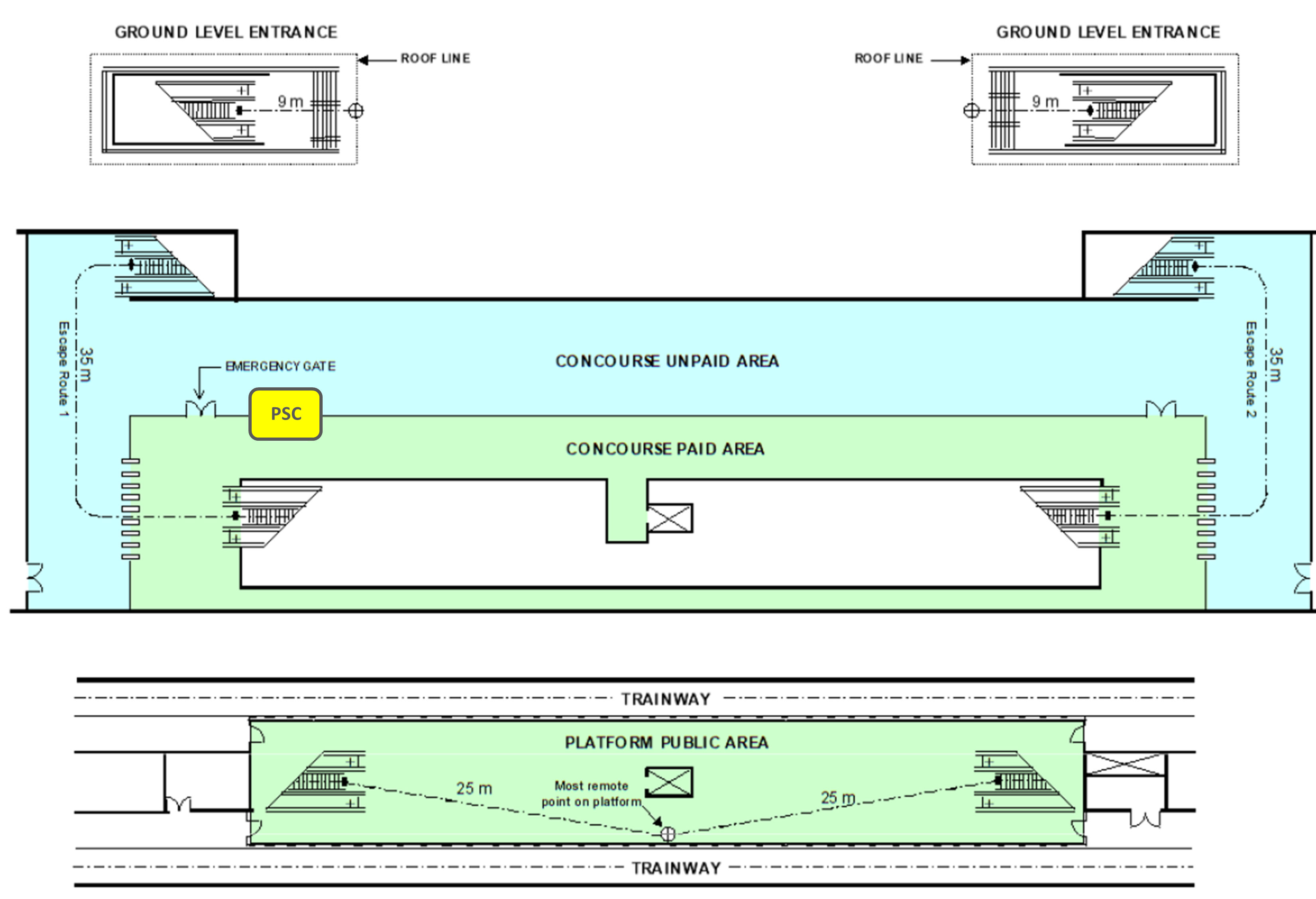
A.2.1 The sample centre platform station shown in Figure A-2.1 is an underground station with the concourse above the platform level but below grade. The platform public area is 60m long to accommodate the train length. The vertical distance from the platform to the concourse is 5m. The vertical distance from concourse to grade is 8m.
The station has two entrances normally used by passengers. Each of these entrances has two escalators of 1m clear width and one stair of 2m clear width. The entrances are covered at grade level to a point 9m beyond the top of the stair landing.
The station concourse level has one paid area separated from the unpaid area. At two ends of the paid area, there are 8 electronic fare gates and a 1m wide emergency gate. The open well at the centre of the concourse level communicate with the platform level. Each end has one stair of 2m clear width and two escalators of 1m clear width. Station ancillary areas are located at the two ends of the platform and concourse level.
The station occupant load is 1200 persons.
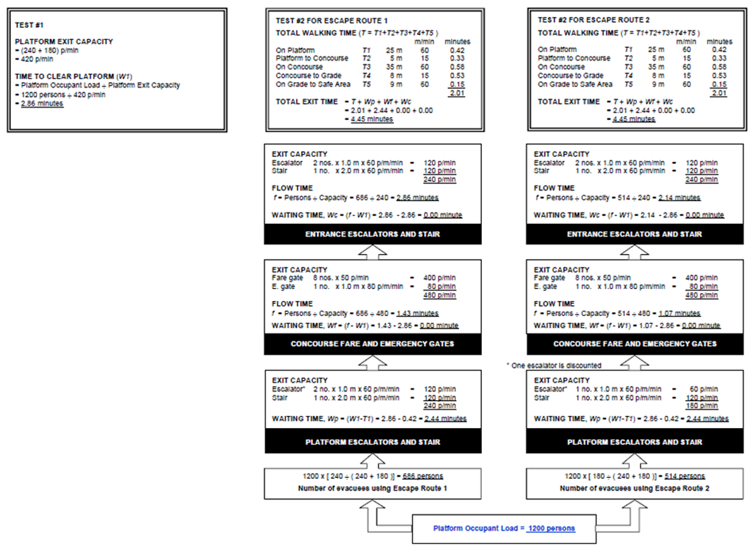
In Test #1 of Figure A-2.2, the time to clear the platform is found to be 2.86 mins. This meets the requirement of Cl.2.2.3d.. The sample calculation shows the effect of discounting one of the escalators from platform to concourse for the escape route to the right of the station.
In Test #2 of Figure A-2.2, the time to reach a point outside any enclosing structure for Escape Route 1 and Escape Route 2 are found to be 4.45 mins. They meet the requirement of Cl.2.2.3e..
Additional calculations must also be made to examine the results of discounting an escalator at other locations to verify that the exit time under those conditions can still comply with Cl.2.2.3e..

Figure A-2.1: Centre Platform Station

Figure A-2.2: Egress Analysis
 ) or https:// as an added precaution. Share sensitive
information only on official, secure websites.
